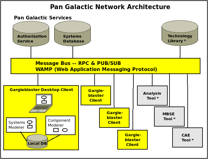
The Pan Galactic Engineering Framework is a Collaborative Model-Based Engineering (MBE) framework, consisting of a desktop client (Gargleblaster), a network message bus (Crossbar), and a repository service (VGER) that provides access to a Systems Database, as shown in the diagram below.
This reference document is primarily focused on the application structure of the Gargleblaster desktop client. It includes a Glossary) of terms related to the Pan Galactic domain objects that Gargleblaster creates and manages.

In the manufacturing domain, there are many terms for the concept of designed artifact, e.g. System, Subsystem, Component, Part. The general term most widely used in engineering data standards is “Product” – hence, PGEF uses the term Product for all of those items. The use of the more general term Product is simply a convention and in no way limits the types of information and models that can be associated with an artifact, independently of whether it is referred to in some contexts as a System (a complex Product with internal structure and behaviors) and in others a Component (a Product used in the assembly of another Product).
PGEF generally uses the term System in the context of a white box model of a Product (i.e., one in which the internal structures and/or interfaces of the Product are known) and Component in the context of a black box model (in which only the attributes and external shape and/or interfaces are known or relevant). Gargleblaster is designed to support the multi-disciplinary nature of Product models, so for any given Product, Gargleblaster can maintain and track its relationships to multiple white box and black box models. Indeed, it is perfectly normal for a Product to have several types of models, some of which are white boxes and some black boxes, developed and used by discipline engineers in various design and analysis contexts.
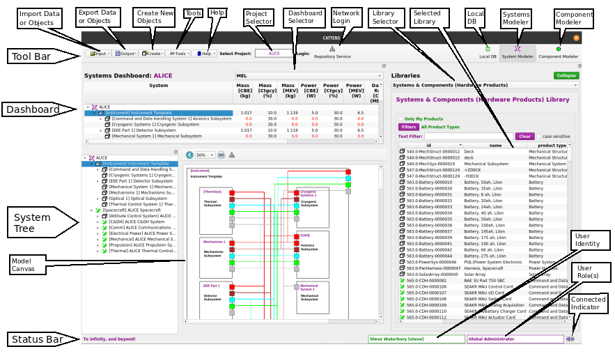
The Gargleblaster application Main Window consists of a Tool Bar, a central area with various widgets (such as a Dashboard and a System Tree), and a Status Bar at the bottom, which displays messages regarding network interactions and local database events. Many of the labels and buttons shown have “tooltips” (brief help messages that display when the mouse hovers over them). The figure below shows the elements of the user interface when it is in Systems Modeler mode (user interface modes are explained in detail in the User Interface Modes section, below).
The Input menu provides functions to import data or objects.

Enables the user to import all Requirements from an Excel file that was created using the
Clicking this menu item opens a file dialog so the user can select the file to be imported – when the file is selected, the import process begins. Progress is shown by messages in the status bar.
Enables the user to import selected Products from an Excel file. Clicking this menu item opens a file dialog so the user can select the file to be imported.
Enables the user to import a Project (including all its systems and their assemblies) from a file that was created using the Export Project to a File function.
Clicking this menu item opens a file dialog so the user can select the file to be imported – when the file is selected, the import process begins. Progress is shown by messages in the status bar.
Note that although Gargleblaster can import data from a file that has been created using the Export Project to a File… function (which uses a Gargleblaster-specific serialization), importing data that contains objects that were created by other users should not be done by a non-administrative user because of data synchronization issues with the repository: when the user logs in after importing data, the repository sync process will delete any objects not created by the local user unless they already exist in the repository. That is because the repository only allows users to save objects that they create or are authorized to modify, so when Gargleblaster sends data to the repository for synchronization and the data contains an object that was created by another user but the object is not present in the repository, the repository assumes that the object was deleted either by its creator or by an authorized user, so the repository will not save the object and will instruct Gargleblaster to delete the object from its local database.
For the above reasons, if a user wants to recreate all or part of a saved database or project that contains objects created by other users, the best way to do that is to send the exported file to the repository administrator and ask them to load it; then if the user is assigned a role in the project(s) or organization(s) that own(s) the data, their Gargleblaster client will receive that data in the sync process the next time the user connects to the repository.
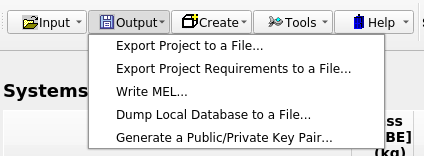
The Output menu provides functions to export data or objects.
Enables the user to export the currently selected Project (including all its systems and their assemblies) to a file, which can be saved as a backup. The exported file can later be imported into Gargleblaster using the Import Project from a File function – however, see the important note about importing data.
The format of the exported file self-describing and it therefore has some degree of schema-independence. releases will sometimes involve internal database schema (ontology) changes, and since the exported file is schema-independent, the Import Project from a File function can migrate the imported data to the new schema – however, see the important note about importing data.
Enables the user to export the set of Requirements applicable to the currently selected Project to a file, which can be saved as a backup. The exported file can later be imported into Gargleblaster using the Import Project Requirements from a File function – however, see the important note about importing data.
Generates a Bill of Materials or Master Equipment List (MEL) derived from the systems, sub-systems, and components as they are assembled for the currently selected Project.
Clicking this menu item displays a file dialog so the user can select an appropriate name and location for the file that is created.
Writes the complete local database to a file as a set of serialized objects, which are serialized in thestandard serialization format and encoded into YAML. Clicking this menu item displays a file dialog so the user can select an appropriate name and location for the file that is created.
The Create New Objects menu provides functions to create new Products (a.k.a. Systems, Components), Functional Requirements, Performance Requirements, and Tests.

Displays the System / Component Wizard (follow link to that section for details.)
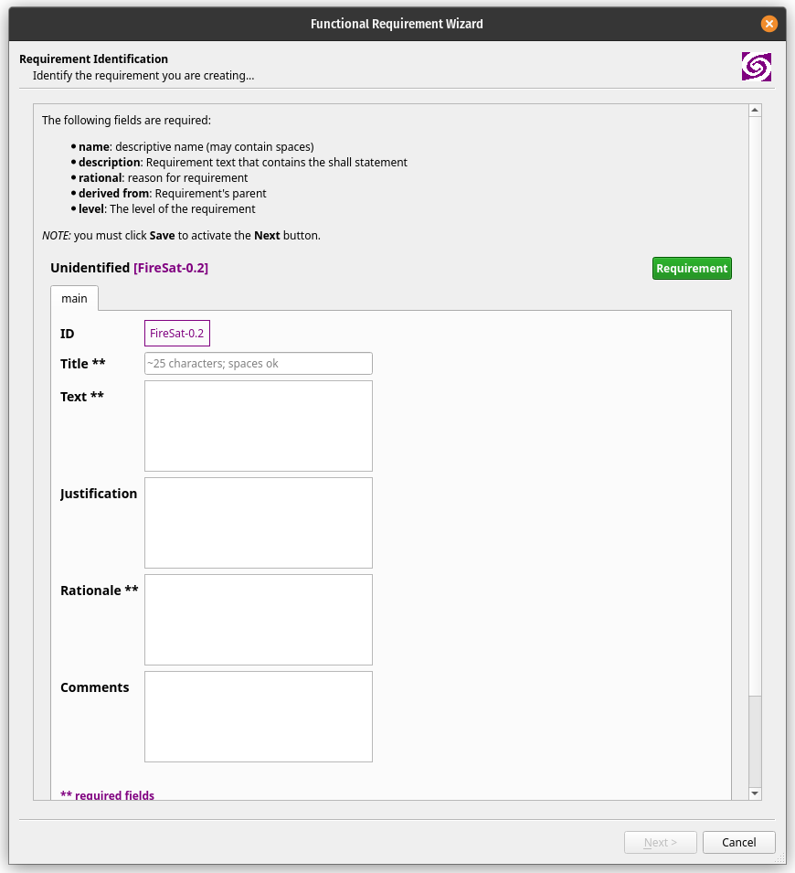
Displays a wizard (see figure below) in which the user can create a new Functional Requirement.
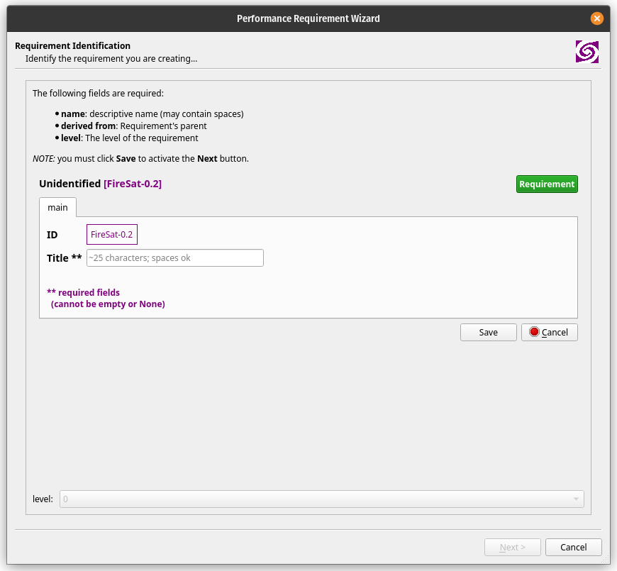
Displays a wizard (see figure below) in which the user can create a new Performance Requirement.
A Requirement is typically owned (defined and managed) by an Organization, and when a new Requirement is defined, Gargleblaster assigns the currently selected Project as its owner (the owner field is on the info tab of the Object Editor) – note that that is just a default assignment of owner, and can be modified by the creator of the Requirement (i.e. the user who is editing it). The id attribute also gets a default prefix from the Project id – for example, the figure shows the id prefix as “SANDBOX”, since it was created while the SANDBOX Project was selected.
It is also worth noting that, as explained in the Project Requirements Manager section below, the Project Requirements Manager function will display all Requirements for which the owner is the currently selected Project.
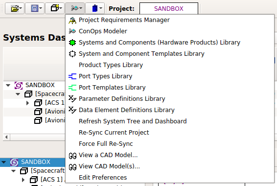
The Tools menu provides functions for various tasks such as editing the user’s preferences, displaying libraries in separate windows, and some administrative tasks such as updating Gargleblaster.
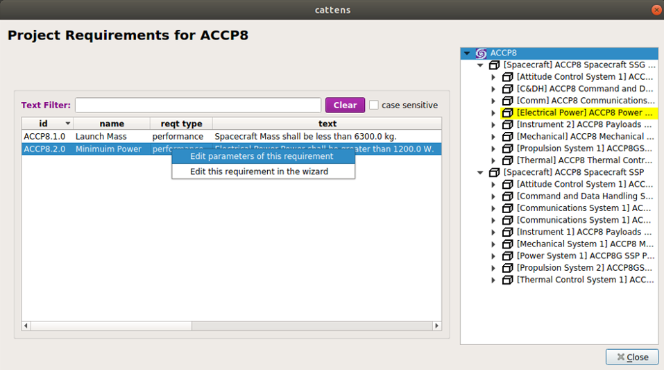
Displays all Requirements for the currently selected Project in a dialog window. The user can filter the displayed items by typing a string into the Filter field – filtering will be case-sensitive if the case sensitive box is checked, otherwise it will be case-insensitive (the default).
As shown in the screen capture below, selecting a requirement on the left side (by left-clicking on it) will highlight in yellow the system/subsystem in the assembly tree on the right side to which the requirement has been allocated (assuming it has been allocated). The screen capture also shows the context menu that is displayed by right-clicking on a requirement, if you have edit privileges for the requirement based on your assigned role(s) in the project. If you do have such privileges, you can either edit just the performance parameter associated with the requirement (second screen shot below), or import the requirement into the Requirement Wizard to edit other properties of the requirement.
The ConOps Modeler tool provides a drag and drop interface for the creation of mission timelines.
The Systems and Components (Hardware Products) Library menu item brings up the library in a dialog window. The same Systems and Components (Hardware Products) Library is also displayed in the “Libraries” panel on the right side of the Main Window (see Main Window Elements). Some reasons why you might want to display the library in a separate dialog window include:
you need a wider view, including more fields (columns) than are shown in the Libraries panel on the right side;
you need to view one of the other libraries at the same time, such as the Parameter Definitions Library, the System and Component Templates Library, or the Port Templates Library.
Note that the user can click and drag any item in the library and add it as a component to another system by dropping it onto either the system’s node in the System Assembly Tree or its block in the Block Model. See the System Assembly via Drag and Drop section for details on how the drag-and-drop assembly process works.
The user can sort the Systems and Components (Hardware Products) Library on any column by clicking on the column heading. The user can filter the displayed items by typing a string into the Text Filter field – filtering will be case-sensitive if the case sensitive box is checked; otherwise it will be case-insensitive (the default). The user can view details about any item in the library by right-clicking on the item (which displays a context menu) and then selecting “View this object”, which will display the item in the Object Viewer/Editor.
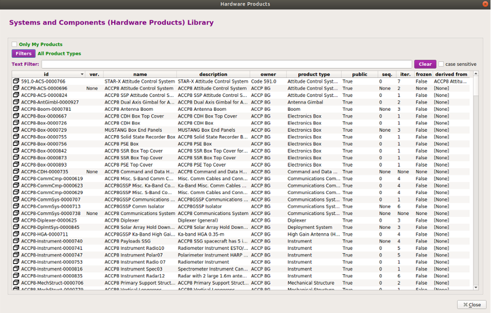
Displays all System and Component Templates in a dialog window.
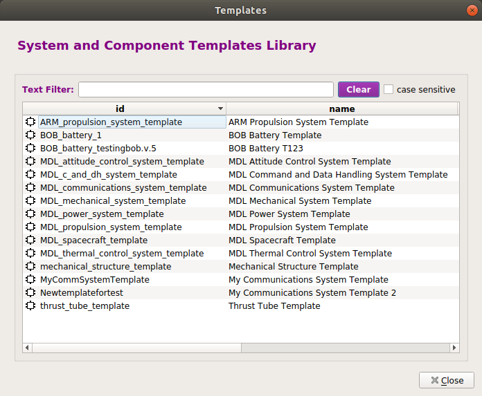
In Component Modeler mode, you can use drag-and-drop to create a new system from a Template: simply drag the Template from the System and Component Templates Library and drop it onto the Product Info Panel – this will create the new system, put its information into the Product Info Panel and the Object Viewer/Editor, and create a block for it on the Diagram Canvas. Since you are the creator of the new system, you can edit it in the Object Viewer/Editor and give it components by drag/dropping them onto its block in the Diagram Canvas.
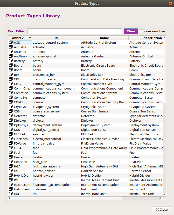
Displays all Product Types in a dialog window. This library is used in assigning a value to the product_type attribute of any component or system. It is only made accessible here as a dialog for information, in case you want to see the definition for any Product Type.
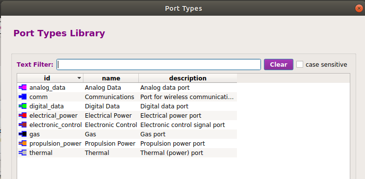
Displays all Port Types in a dialog window.
In Component Modeler mode, you can use drag-and-drop to add a Port to a system or component: simply drag the Port Type from the Port Types Library, drop it onto the system or component’s block in the Diagram Canvas, and the new Port will be created.
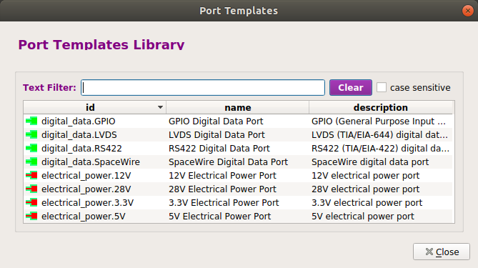
Displays all Port Templates in a dialog window.
In Component Modeler mode, you can use drag-and-drop to add a Port to a system or component: simply drag the Port Template from the Port Templates Library, drop it onto the system or component’s block in the Diagram Canvas, and the new Port will be created.
The advantage of using a Port Template instead of a Port Type is that a Port Template has a parametric value assigned (e.g. a 28 Volt power port will have a Voltage parameter value of 28 assigned), whereas a Port Type has no specific parameter values, but rather it is intended to have parameters and values assigned after it is created. So a Port Template is more useful when a “standard” port with a characteristic parameter value is needed and a template with that value exists in the library.
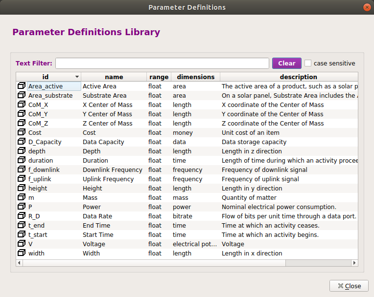
Displays the Parameter Definitions Library in a dialog window. The Parameter Definitions Library can also be displayed in the “Libraries” panel on the right side of the Main Window (see Main Window Elements). Reasons to want the Parameter Definitions Library displayed in a separate window include:
you need a wider view, including more fields (columns) than are shown in the Libraries panel on the right side;
you need to view one of the other libraries (Systems and Components (Hardware Products) Library or System and Component Templates Library) simultaneously with the Parameter Definitions Library.
The user can sort the Parameter Definitions Library on any column by clicking on the column heading. The user can filter the displayed items by typing a string into the Filter field – filtering will be case-sensitive if the case sensitive box is checked; otherwise it will be case-insensitive (the default). The user can view details about any item in the library by right-clicking on the item (which displays a context menu) and then selecting “View this object”, which will display the item in the Object Viewer/Editor.
The Parameter Definitions Library supports drag-and-drop: the user can click and drag any item in the library and drop it onto the parameters panel in the Object Viewer/Editor to assign a Parameter to an object. See the Object Viewer/Editor section for details on how the drag-and-drop process for adding a Parameter works.
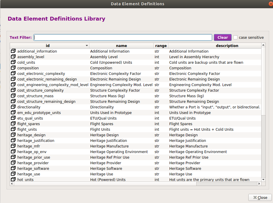
Displays the Data Element Definitions Library in a dialog window. The Data Element Definitions Library can also be displayed in the “Libraries” panel on the right side of the Main Window (see Main Window Elements). Reasons to want the Data Element Definitions Library displayed in a separate window include:
you need a wider view, including more fields (columns) than are shown in the Libraries panel on the right side;
you need to view one of the other libraries (Systems and Components (Hardware Products) Library or System and Component Templates Library) simultaneously with the Data Element Definitions Library.
The user can sort the Data Element Definitions Library on any column by clicking on the column heading. The user can filter the displayed items by typing a string into the Filter field – filtering will be case-sensitive if the case sensitive box is checked; otherwise it will be case-insensitive (the default). The user can view details about any item in the library by right-clicking on the item (which displays a context menu) and then selecting “View this object”, which will display the item in the Object Viewer/Editor.
In Systems Modeler mode, re-generates the assembly tree and dashboard from the local database. (Should only be needed in the rare case of an incomplete synchronization operation.)
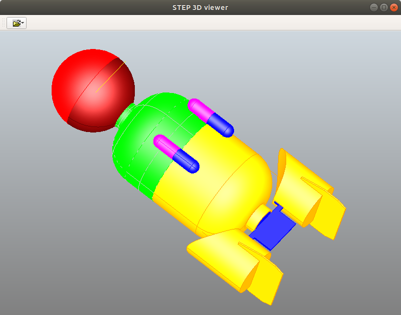
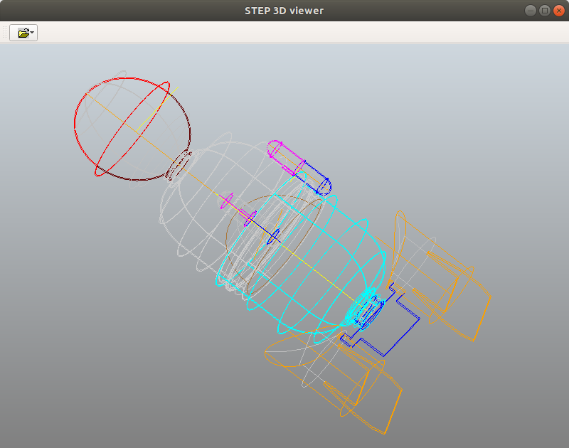
Displays a file dialog in which the user can select a STEP file (also known as a “part 21 file”), which should have a suffix of .p21, .stp, or .step. When a file is selected, the CAD Viewer attempts to read it and, if successful, renders and displays the model. The CAD Viewer is a 3D Viewer with rotate, zoom, and translate functionality. The viewer can render models that follow either of the STEP protocols for Mechanical CAD: AP203 or AP214. The OK and Cancel buttons both do the same thing: close the viewer.
Displays a dialog in which the user can edit some settings for customization. Any values set in the Preferences dialog take effect when the dialog is accepted (i.e., the OK button is clicked), and they are saved between sessions.
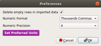
Options:
Delete empty rows in imported data
(what it says)
Numeric Format
Specifies the format options for numeric Parameter values:
Numeric Precision
Specifies the number of digits to be regarded as significant in Parameter values. Options are any integer value from 3 to 9, with 3 being the default.
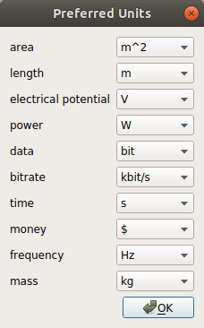
Preferred Units Specifies for each available dimensionality, which units will be used in displaying the Parameter values that have those dimensions. When the unit preferences have been changed and both the Preferred Units and the Edit Preferences dialogs have been accepted (OK has been clicked on both), any dashboard parameter values that have the relevant units will immediately be converted and displayed in the new preferred units.

Clicking the Help button (which has a tiny TARDIS icon) displays a menu with 3 items: “User Guide”, “Reference Manual”, and “About” (which displays the version).

Clicking the Project Selector button displays a list of the currently known Projects to which the user has access.
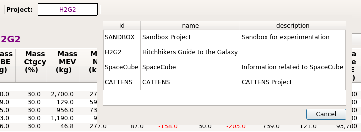
Right-clicking the Project Selector button displays a context menu (shown below). The first option in the menu will be New Project, which if selected will display the New Project Dialog, in which the user can create a new Local Project. If the user is the creator of the currently selected Project and it is a Local Project, the second menu option will be Delete Project. Note that if the user deletes a Project, the items created within that project will continue to exist – only the Project itself is deleted.

The Gargleblaster GUI has four interface modes of operation:
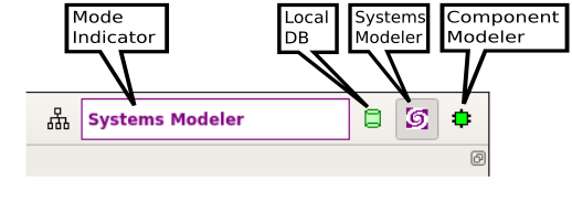
A mode is entered by clicking on one of the four Mode Buttons in the top right corner of the user interface, as shown in the figure below. Just to the left of the Mode Buttons is the Mode Indicator, which shows the currently selected mode. The buttons are shown here with Systems Modeler mode selected. When you exit Gargleblaster, it will remember the mode you are in and will return you to that mode the next time it starts up.
Component Modeler mode is intended to provide convenience for the user when viewing and/or editing Components, Systems, or library Products.
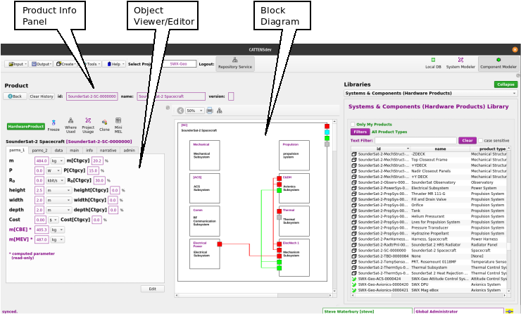
When in Component Modeler mode, the user can select any Product from the Hardware Library, drag and drop it (see figure below) from the library onto the Product Info Panel (the upper panel in the Main Window), as shown below, and that Product will become the “subject” of the Component Modeler: its id, name, and version will be displayed in the Product Info Panel, its full set of Parameter values and metadata will be shown in the Object Viewer/Editor Panel in the left panel, and its Block Model will be shown in the central Diagram Canvas. (In the current version of Gargleblaster, the Diagram Canvas is not editable; in a future version it will be editable.)
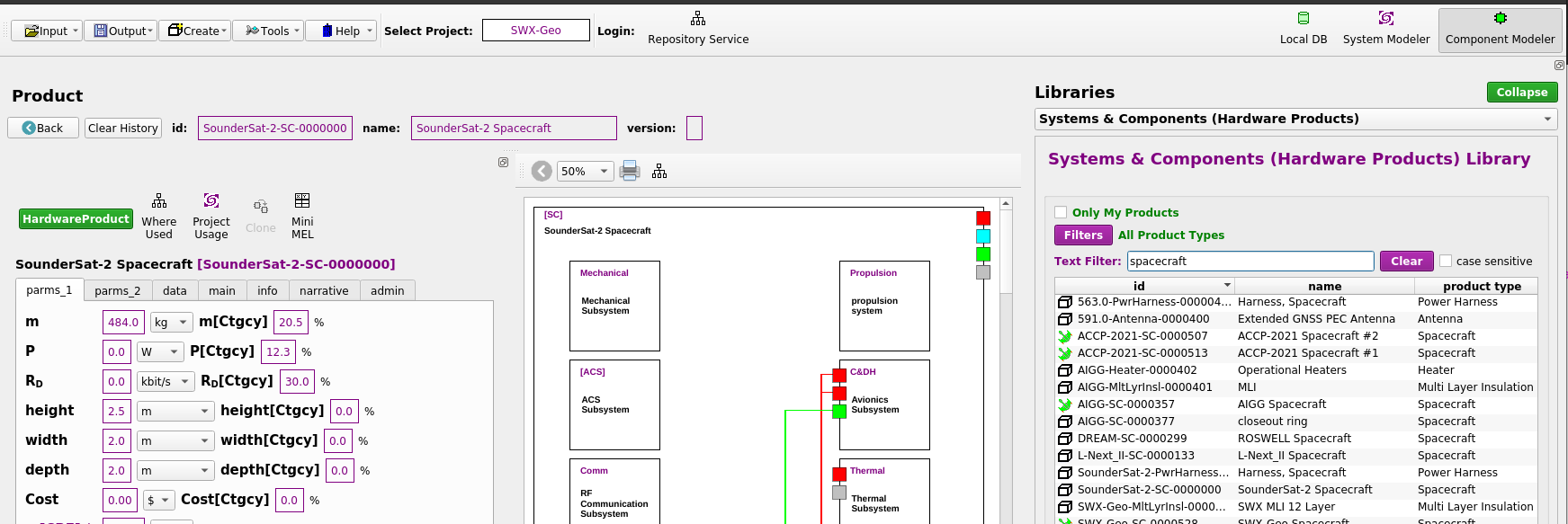
Once a product has been brought into the Component Modeler, it can be viewed and/or edited (if the user has edit permission) in the Object Viewer/Editor panel – see Object Viewer/Editor for more detail.
Systems Modeler mode is intended to provide convenience for the user when viewing and/or editing Systems, and in particular when constructing an assembly structure for a system. In Systems Modeler mode, the main window looks like the figure below:

The System Tree (bottom left panel) is an editable widget that supports drag and drop. The Systems Dashboard (top panel) is automatically synced with the System Tree and displays an expandable table of system parameters that is computed and updated in real-time, even in collaborative operations – i.e. when several Gargleblaster clients are connected via the message bus and are collaboratively building a system assembly.
To add a component to a node in the System Tree, the user can drag an item from the Systems and Components (Hardware Products) Library (right panel) and drop it onto the node – being careful to drop the item only when the target node is highlighted, as shown below:
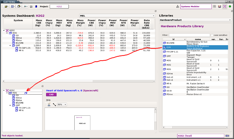
When the mouse button is released, the item (in this case an Illudium Q-36 Explosive Space Modulator) will be added as a component (a.k.a. “subsystem”) of the node on which it was dropped (in this case, the Heart of Gold Spacecraft), as shown in the figure below:
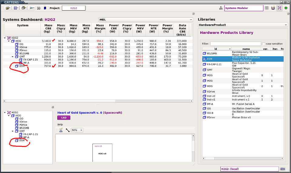
Note that the Systems Dashboard has automatically updated with the new subsystem and the cumulative parameters have been recomputed. In the example shown, Numeric Precision (see Edit Preferences) has been set to 3, so the total is rounded to 3 significant digits.
Nodes in the System Tree can be right-clicked to display a context menu:
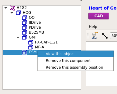
View this object displays the item in the Object Viewer/Editor
Remove this component removes the item from its position in the System Tree but leaves that position as an “empty bucket” in the assembly that is labelled with “TBD [Product Type]”, where Product Type is the Product Type of the item that was removed, as shown below:
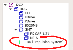
The green “bucket” indicates that there is a role for a product of that type in the system. Now an item can be dragged and dropped from the [Hardware Products Library] into the empty bucket, but its Product Type must match the one specified for that position. If the item dropped has the correct Product Type it will simply “fill” the bucket (i.e., assume that position in the assembly).
The third option in the context menu:
Local DB mode provides a view into the local database. The database table names (DB Tables) are listed on the left side; clicking on a db table name displays its objects (Objects) in the tablular widget on the right.
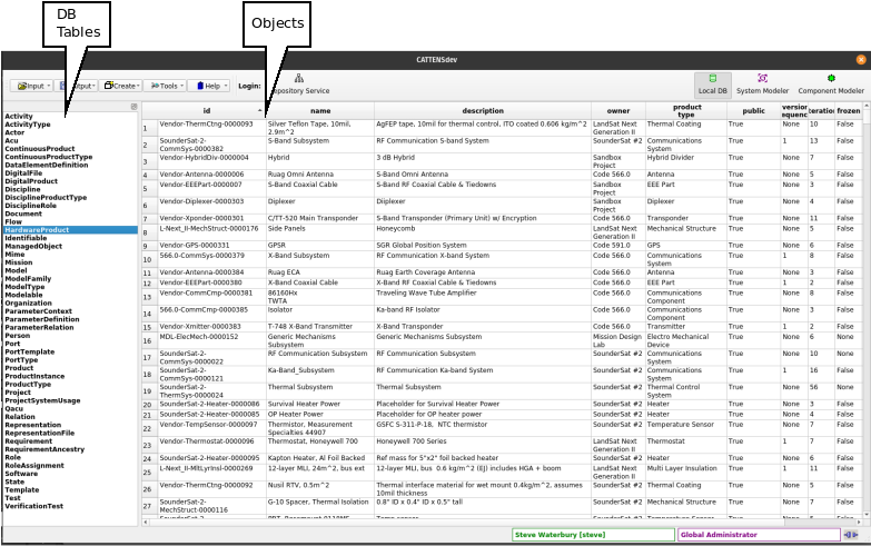
Any row in the Objects table can be double-clicked to display it in an Object Viewer/Editor. The Objects table can be sorted on any column by clicking on that column’s heading. Columns can be rearranged by drag/drop (but the new ordering will not be retained).
Data Mode activates the MEL Tool. [Documentation in progress …]
The Object Viewer/Editor provides an interface to all properties and parameters of an object. In View Mode (shown here) any user can inspect any object in Gargleblaster. If the user has edit permission for an object, an Edit button will be displayed (see Edit Mode section, below).
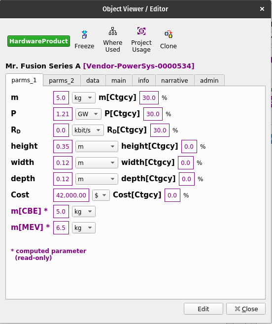
The Object Viewer/Editor dialog can be displayed in the following ways:
In Component Modeler mode, by right-clicking on any object in the Library Panel (right side of the Main Window) and selecting View this object in the context menu;
In Systems Modeler mode, by right-clicking on any object in either the Library Panel (right side of the Main Window) or the System Tree (lower left panel) and selecting View this object in the context menu;
From the Systems and Components (Hardware Products) Library, Parameter Definition Library, Product Types Library, or Template Library, by right-clicking on any object and selecting View this object in the context menu;
In Local DB mode, by double-clicking on any object in the Objects panel (right side).
Note that the Object Viewer/Editor has is exactly the same interface and functionality (and is indeed the same widget) as the Object Viewer/Editor panel in the Component Modeler interface:
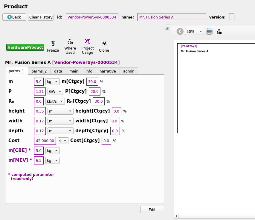
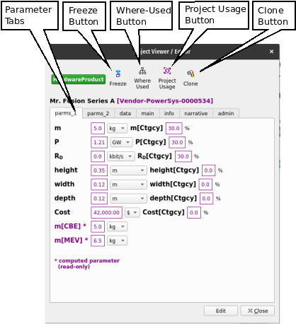
Parameter Tabs display the object’s parameters. As many parameter tabs as necessary will be created – typically, at least 2 parameter tabs are needed, to accommodate the minimum default parameters for Mass, Power, Data Rate and their associated variants.
Clone Button displays a dialog to begin the process of cloning the object – see Cloning.
Models Button – not implemented yet.
(will display a dialog that gives the user options to display Models associated with the object, if there are any, such as CAD models, block models, etc.)
Other Tabs include:
The Object Viewer/Editor usually initializes in View Mode (the exceptions being in the Cloning process and the [Component Wizard], in which the process requires Edit Mode). If the user has edit permission for the object being viewed, there will be an Edit button at the bottom of the Object Viewer/Editor interface that will switch the interface to Edit Mode.
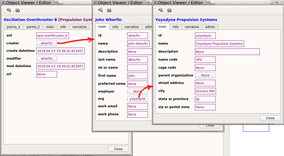
In View Mode, the user can explore the object by selecting various tabs in the interface. If an attribute of the object is another object, that attribute’s value will appeaar as a button, which if pushed will display the related object in another Object Viewer/Editor. In the example below, the Oscillation Overthruster B object has the create attribute “whorfin”, which has been clicked to display the Person object John Whorfin, whose org attribute yoyodyne points to the Organization object Yoyodyne Propulsion Systems:
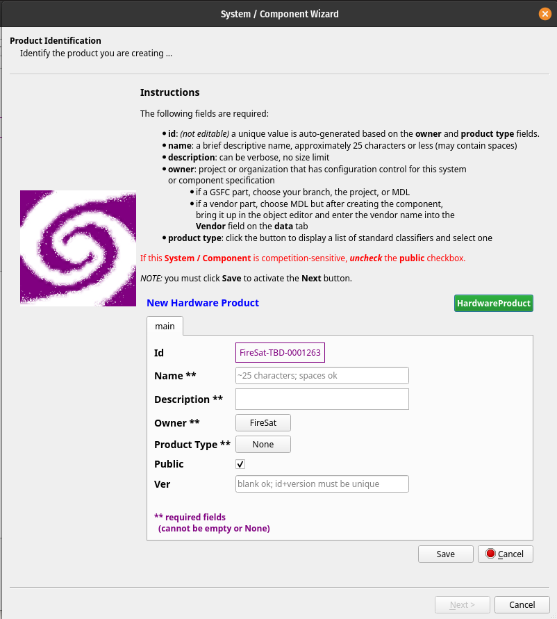
The System / Component Wizard provides a guided process to create a new System or Component (a.k.a. Product).
Note that any new system or component that is marked public will automatically be added to the Systems and Components (Hardware Products) Library and will then be usable in the assembly of any new system. Non-public (sensitive or proprietary) systems or components (i.e. those for which the public field is not checked) will only be visible to users who have been assigned roles in their owner project or organization.

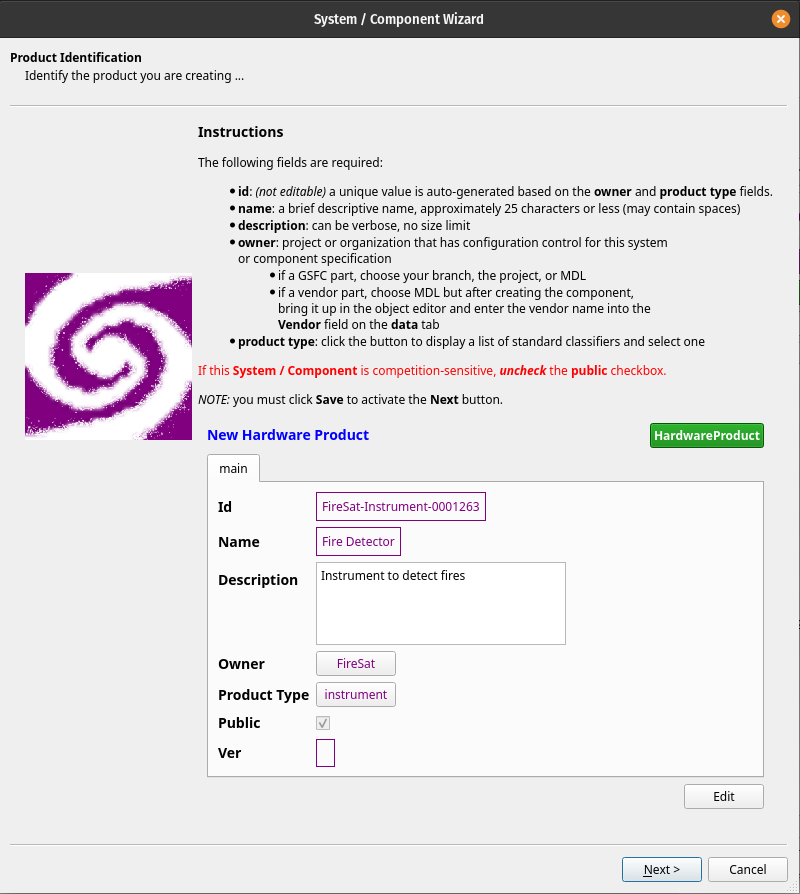
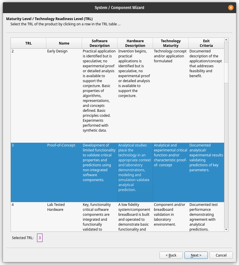
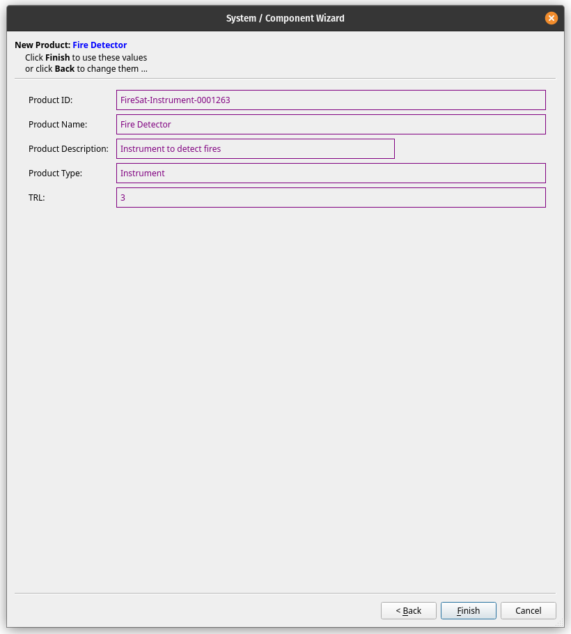
Gargleblaster has 2 ways to do that:
A Functional Requirement is a Requirement that specifies a feature or behavior that must be implemented by a system.
A MEL is a specialized bill of materials report, which takes the form of an Excel file in the standard format specified in “GSFC’s MEL Guidance for Proposals” (Nov 2016 version). See the Gargleblaster Write Mel function.
A computational representation of the properties and/or behaviors of a concept or a real-world thing. A Model can be used for analysis, simulation, description, specification, or presentation of some aspect(s) of an object. Model in the engineering domain generally maps to STEP (ISO 10303) product_definition, but there may be other mappings for particular STEP Application Protocols and other types of models. (Note that the characteristics of a Model can be the subject of a Model at a higher level of abstraction; the higher-level Model in this context is sometimes referred to as a meta-model relative to the Model whose characteristics it models.)
A Parameter is a characteristic of an object that is being modeled. Every Parameter has an associated Parameter Definition that specifies its symbol, its datatype (float, integer, text, or boolean), and its dimensions (which, if applicable, constrain its units).
A Parameter Definition specifies the symbol (a.k.a. id), datatype, dimensions (if applicable), and textual description of a Parameter.
A Performance Requirement is a Requirement that places a constraint on some measurable property or behavior of a system.
The Product object (a.k.a. System, Subsystem, Component, Part) in Gargleblaster corresponds to a specification or data sheet – i.e., an “as-designed” Product. Product objects can be either black box entities, such as vendor parts whose internal components and structure are not known to the user, or white box entities, such as in-house systems whose internals are known. In-house built or customized Products may be explicitly versioned in Gargleblaster using the Product version attribute, but that is not required. For externally-specified (e.g. vendor) Products, whose versioning is not controlled in-house, the version attribute is not used but the item’s version may be inferred from its other attributes, such as its specification number, drawing number, manufacturer part number, or specification part number.
A functional category or classification of a Product. Product Types are labels which are intended to be a convenience for the user in searching for, filtering, or grouping Products. Product Types can also be associated with a set of Parameter Definitions so that when a new Product of a specified Product Type is created, it will be assigned the appropriate Parameters by default. The relationship between Product Types and Parameter Definitions is many-to-many – i.e., a Product Type will typically have multiple Parameters, and a Parameter will typically be associated with multiple Product Types.
An activity that has the purpose of producing and/or maintaining something, and which involves contributions from Persons and Organizations.
A Requirement is the specification of a feature, a behavior, or a constraint to be satisfied by a Product or Activity.
STEP (ISO 10303) is an International Standard for the computer-interpretable representation and exchange of product data. Its objective is to provide a mechanism that is capable of describing product data throughout the life cycle of a product, independent from any particular system. The nature of this description makes it suitable not only for neutral file exchange, but also as a basis for implementing and sharing product databases and archiving.
Time And Relative Dimension In Space, a fictional time machine and spacecraft that appears in the British science fiction television programme Doctor Who and its various spin-offs.
A Template is a pre-defined structure from which a Product can be created. A Template has a Product Type but most importantly it can include an internal component structure, so that when a new Product is created from the Template, the new Product will not only have the same Product Type (and Parameters) but will also replicate the component structure of the Template.
A Test is a type of Activity consisting of a specified environment, specified inputs and measurable expected results (synonymous to SysML: testCase, modeled by a SysML Interaction).