The first time Gargleblaster starts up, it will create a directory called either gargleblaster_home (for a production version) or gargleblaster_home_dev (for a development version). In that directory it will save its configuration and create a local database.
This step is only required if you plan to connect Gargleblaster to a pangalactic.vger repository service.

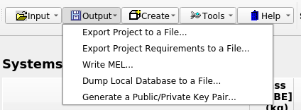
… select the menu item Generate a Public/Private Key Pair This generates a pair of encrypted keys that are used in the single-sign-on process that Gargleblaster uses to log in to a pangalactic.vger repository service.
C:\Users\[your userid]\gargleblaster_home\public.key
… and for a development version on Windows it is here:
C:\Users\[your userid]\gargleblaster_home_dev\public.key
On the Mac, the locations are:
/Users/[your userid]/gargleblaster_home/public.key and /Users/[your userid]/gargleblaster_home_dev/public.key
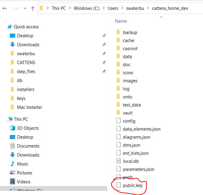
(After you email it to the admin, you no longer need the public.key file.)
The private key is a file called gargleblaster.key which is located in your profile folder (a.k.a. your “home directory”). Take care not to delete it because it is used by Gargleblaster and will be used by any future version of Gargleblaster you install. The same gargleblaster.key file is used by both Gargleblaster and Gargleblasterdev.
After you have sent your public.key file to the repository administrator and the administrator has added it to the repository authentication database, you can log in.
When the Repository Service icon in the Tool Bar is clicked, Gargleblaster will use the gargleblaster.key file to do a transparent single-sign-on login to the repository service. Note that the Repository Service icon is a toggle – you use it to log in or to log out.
When you log in to the repository service, Gargleblaster will:
Once the initial sync is completed, Gargleblaster will listen for events, such as additions or modifications of objects, and will update in real-time.
Whenever you switch to a different project using the Project Selector, the Project sync operation (step 4 above) is executed for the newly selected Project.
The Gargleblaster GUI has 3 interface modes of operation:
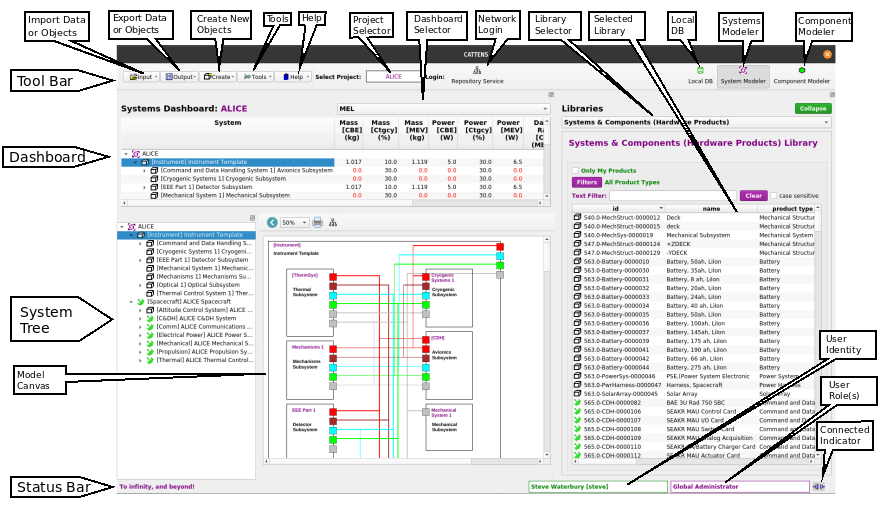
You can switch between these modes by clicking on one of the Mode Buttons in the top right corner of the window, as shown in the figure below. The currently selected mode is indicated by which button is in the clicked state (toggled on). The buttons are shown here with System Modeler mode selected (that is the default mode). When you exit Gargleblaster, it will remember the mode you are in and will return you to that mode the next time it starts up.

System Modeler mode is mainly designed to provide convenience for viewing the current state of an entire System assembly structure and its subsystem and component parameters, which are shown in the Systems Dashboard. Although it is possible to edit objects in Systems Modeler mode if your assigned Project Role(s) give you edit permissions, in general it is easier and more efficient to do such edits in the Component Modeler mode.
Note that the system assembly tree structure, block diagram, and Systems Dashboard are automatically updated in real-time when any subsystem is added, modified, or deleted by anyone who is connected to the repository. Modified parameters are updated in real-time and any rolled-up parameters are recomputed and displayed in the Systems Dashboard in real-time.
The System Modeler mode interface looks like the figure below:
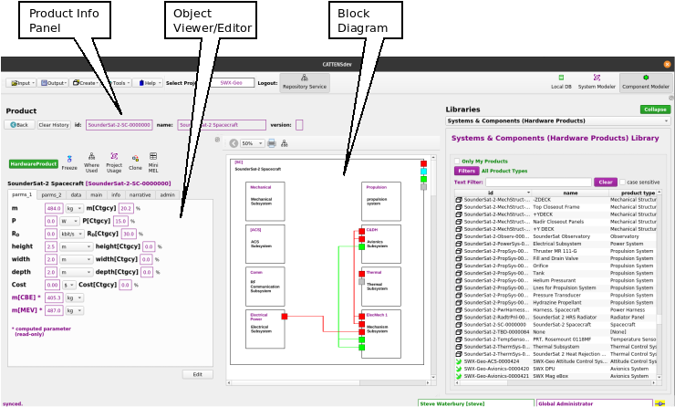
Component Modeler mode is intended to provide convenience for viewing and editing Systems, Components, or library Products. The Component Modeler has 2 main purposes:
To view the parameters and structure (components) of any item in the Systems & Components Library (does not require edit privileges).
To edit a System or Subsystem – see details in [Use Component Modeler Mode to Edit a System or Subsystem], below.
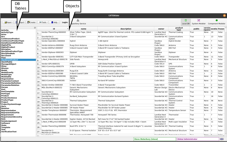
Local DB mode provides a view into the local database. The database table names (DB Tables) are listed on the left side; clicking on a db table name displays its Objects in the tablular widget on the right.
The Object Viewer/Editor provides an interface to all parameters, data elements, and other properties of an object.
The Object Viewer/Editor dialog can be displayed in the following ways:
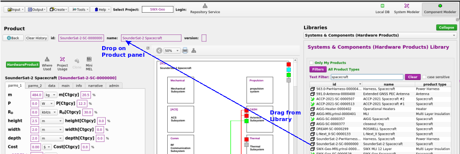
In Component Modeler mode, just click and drag any item from the Systems and Components (Hardware Products) Library, (right panel) and drop it onto any field in the Product panel (upper left) – that will load the object into the Object Viewer/Editor on the left and display its block diagram;
In System Modeler mode, right-click on any object in either the Library Panel (right side of the Main Window), the System Tree (lower left panel), or the block diagram (center) and select View this object in the context menu;
In Local DB mode, double-click on any line in the Objects table (right side).
Note that the Object Viewer/Editor always has exactly the same interface and functionality wherever it is invoked.
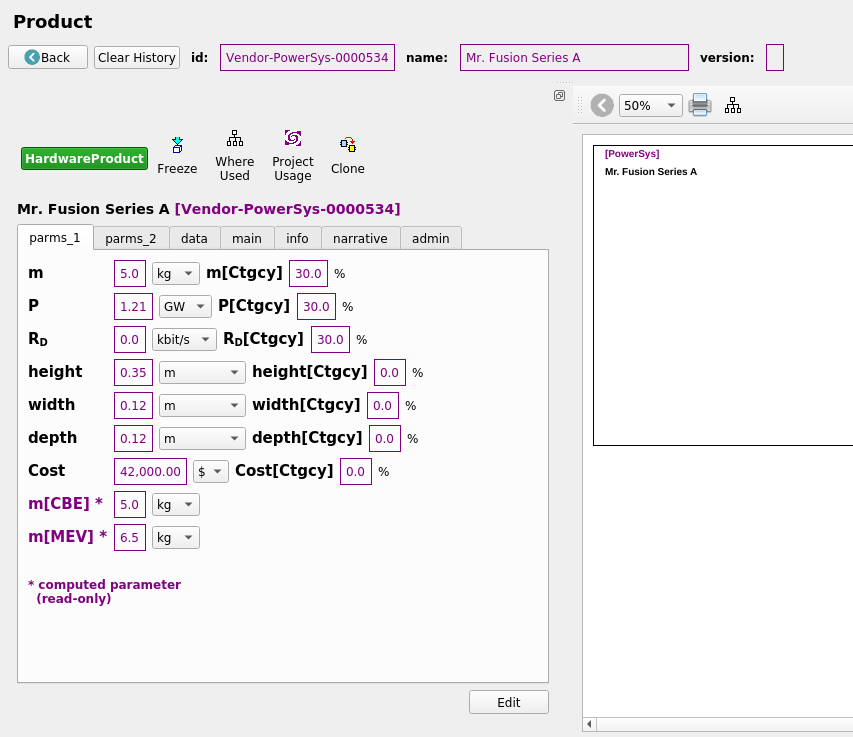
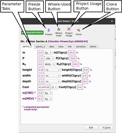
Parameter Tabs display the object’s parameters. As many parameter tabs as necessary will be created to accomodate parameters as they are added – typically, at least 2 parameter tabs are needed, to accommodate the minimum default parameters for Mass, Power, Data Rate and their associated variants.
Freeze Button freezes the object (prevents further editing)
Where-Used Button displays the names of next-higher systems (assemblies) that contain this object as a component.
Project Usage Button displays the names of all projects in which object is used as a system or component.
Clone Button clones the object (creates a copy with the same properties) – see Clone an Object.
The other tabs are:
The Object Viewer/Editor usually initializes in View Mode (the exceptions being in the Cloning process and the System/Component Wizard, in which the process requires Edit Mode). If you have edit permission for the object being viewed, there will be an Edit button at the bottom of the Object Viewer/Editor interface that will switch the interface to Edit Mode.
In View Mode (figure below) you can explore the object by selecting various tabs in the interface. If an attribute of the object is another object, that attribute’s value will appeaar as a button, which if clicked will display the related object in another Object Viewer/Editor.
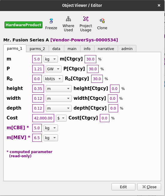
In Edit Mode any fields which are displayed as editable can be edited. Note that some fields are intrinsically read-only, such as computed parameters – for example, the CBE (“Current Best Estimate”) parameters are always computed as a recursive sum of an object’s components’ parameters, so they are read-only and are so annotated.
If you need to assign more parameters or data elements to the object:
Again, this will only work in edit mode: right-click on the label of the parameter or data element you want to delete and select delete.
In Component Modeler mode, you can click and drag any item from the Systems & Components (Hardware Products) Library and drop it onto the fields in the Product panel (see figure below) and it will become the subject of the Component Modeler: its id, name, and version will be displayed in the Product panel, its name and id will become the title in the Object Viewer/Editor Panel (left side) and its full set of Parameter values and other data will be accessible there. Its Internal Block Diagram (equivalent to a SysML IBD) will be shown in the central Block Diagram panel. (If you have edit permission for the product, the Block Diagram will be editable.)
Once a product has been brought into the Component Modeler, it can be viewed and (if you have edit permission for that product) edited in the Object Viewer/Editor panel – see Use the Object Viewer/Editor for more detail.
To add a component, simply drag an item from the Systems & Components (Hardware Products) library and drop it onto any open space within the border of the diagram. Note that you cannot drop an item onto another block in the diagram unless it is a TBD block, meaning that block is unoccupied (it will have a dashed outline).
If you want to modify an existing component block in a diagram (e.g. add sub-components), simply drill down by double-clicking on the component block – the drill down operation will make that component the new subject of the Component Modeler, and if you have edit privileges for that component you will be able to edit it. When you have finished editing the component, you can go back to the previous object (the product that contains the component) by clicking the “Back” button in the Product panel – that will change the subject of the Component Modeler back to the previous object.
To remove a component from an assembly, right-click on its block and select either Remove this component or Remove this function.
Remove this component: removes the product but leaves a TBD block that represents that “function” in the assembly – the TBD block is unoccupied but can have requirements allocated to it, so whatever product is placed into that function should satisfy any allocated requirements. Also, the TBD block will have an associated Product Type that corresponds to its function, and it will only accept products of that Product Type. The TBD block can be removed using the Remove this function context menu item.
Remove this function: removes the component block entirely, even if it is a TBD block.
Gargleblaster has 2 ways to do that:
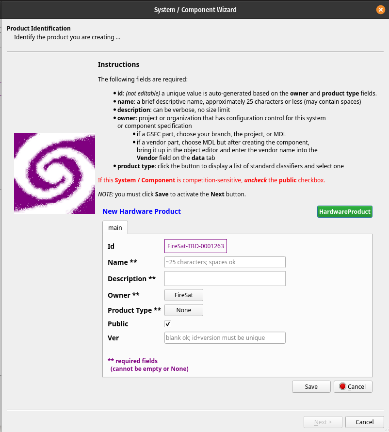
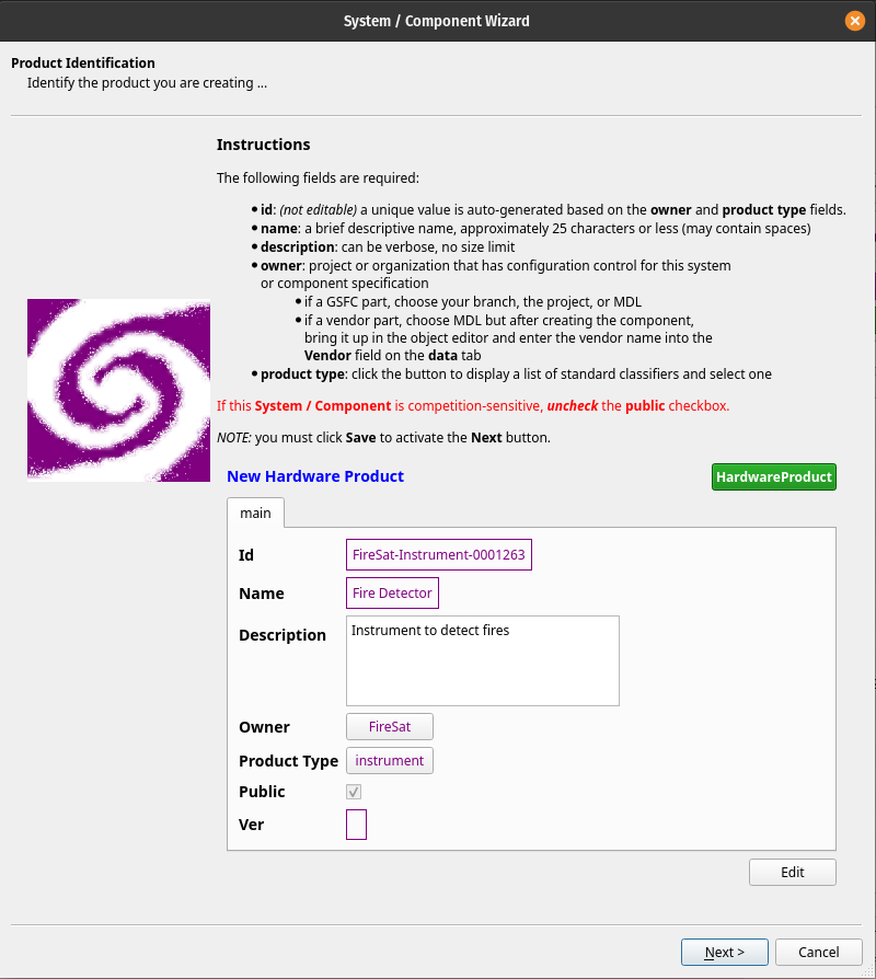
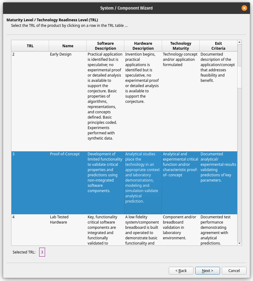
The System/Component Wizard provides a guided process to create a new System or Component (a.k.a. Product).
Note that any new system or component that is marked public will automatically be added to the [Systems and Components (Hardware Products) Library] and will then be usable in the assembly of any new system. Non-public (sensitive or proprietary) systems or components (i.e. those for which the public field is not checked) will only be visible to users who have been assigned roles in their owner project or organization.
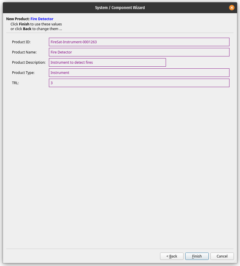
Cloning in Gargleblaster simply means creating a copy of an object. In general, the clone will have the same property values, parameter values, and data values as the original object.
A clone is created by clicking on the Clone button in the Object Viewer/Editor – if the object being cloned is a white box (its components are specified), a dialog will be displayed with various options (see details below); if the object is a black box, Gargleblaster will immediately create the clone and switch to Component Modeler mode with the new clone set as the subject, and you can begin editing it as necessary. The clone will automatically be assigned a new id, but you should edit its name and description fields at least, and edit its component structure as necessary – see [Use Component Modeler Mode to Edit a System or Subsystem] for more information about how to do that.
If the object being cloned is a white box – i.e. it has a specified set of components – then clicking the Clone Button in the Object Viewer/Editor will bring up a dialog with options, as shown here:
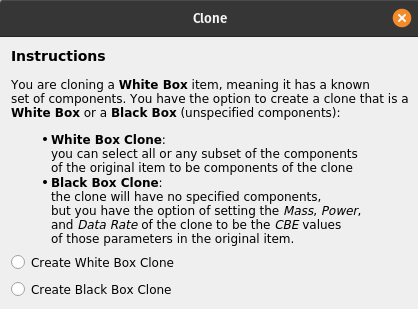
If you select the Create White Box Clone option, the following dialog will be displayed:
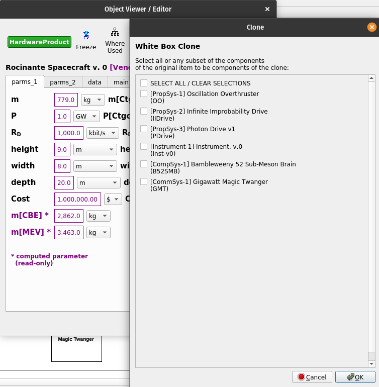
As the instructions say, you can select all components or any subset of them, and the clone will then contain references to exactly the components that you select. Note that the clone’s components will not be copies of the original components, they will be indentical to the components selected – in other words, the components of the clone will be pointers to the library objects that you selected from the original object’s components. If you want the new clone’s components to be different from those of the original object, it is better to select Create a Black Box Clone and then populate the resulting black box with any components you specify, making it into a white box.
If you select the Create Black Box Clone option, the following dialog will be displayed:
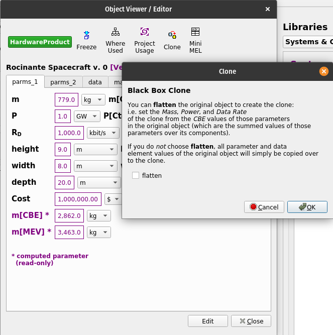
As the instructions say, you can select flatten, in which case the CBE (Current Best Estimate) values of Mass[CBE], Power[CBE], and Data Rate[CBE] for the original object are assigned to the Mass, Power, and Data Rate parameters of the clone. Since the CBE parameters of a white box product are computed as the sum of the CBE parameters of its components, this essentially “flattens” them into the new black box object, which will have the same CBE parameters as the original object but without its components.
If the flatten option is not selected, the clone will simply be assigned the original object’s specified Mass, Power, and Data Rate parameters.
Note that in either case, whether a white box or black box clone is created, the clone will receive all parameters of the original object.
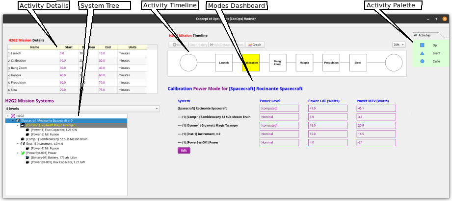
A ConOps defines the sequence of activities that constitute a Mission. The Lead Engineer and Systems Engineer for a project can use the ConOps Modeler to create a timeline on which the Mission Activities are defined, and each Activity can be assigned a duration and can be characterized by a power mode. The features of the ConOps Modeler interface are shown here:
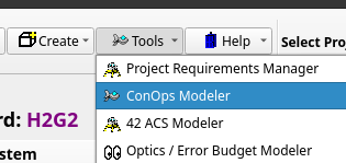
To begin, select the ConOps Modeler item in the Tools menu.
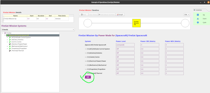
The first time the ConOps Modeler is opened for a new project, it will display an empty Mission Timeline scene, a Mission Details table, and the Mission Systems assembly tree, as shown here:

The first step is to begin adding activities to the Mission Timeline. This can be done by either of 2 methods:

– OR –


Once an activity has been added to the Timeline, its Name, Duration, and Time Units can be edited in the Details table on the left side of the interface simply by clicking on the cell, typing a value, and hitting Return. Note that the Start and End times are computed from the Duration values, so they cannot be edited.
After one or more Activities have been added to the Timeline, power modes can be defined – to do that:
Select an Activity block by clicking on it – it will be highlighted in yellow.
Select a system by clicking on an item in the System Tree (left panel). Typically either an Observatory or a Spacecraft will be selected first, as the highest-level system for which power modes will be defined; in the case of a Spacecraft, its subsystems may each in turn be selected for more detailed power mode definitions. When a system is first selected, you will see the dialog shown here:

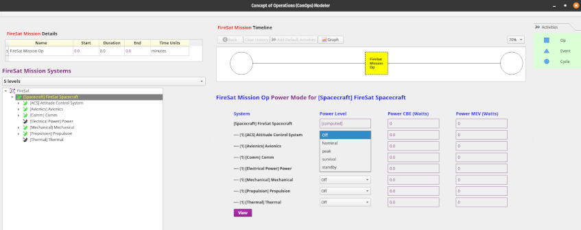
When a power level is specified, the ConOps Modeler looks up the component or subsystem’s specified value for that power level and immediately uses it to populate the corresponding Power CBE and Power MEV columns for that component or subsystem.
The definition of power modes will typically begin at either the Observatory or Spacecraft level, but a subsystem power mode can be defined in terms of the power characteristics of its components – this is done by clicking on the corresponding subsystem in the System Tree in the left panel, where the initial system was selected … a dialog will be displayed asking for confirmation that you wish to define power modes for that subsystem – as shown:
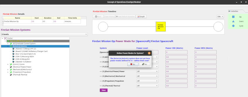
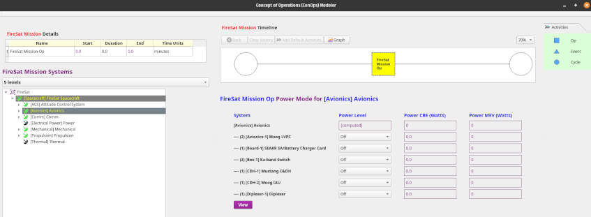
In the example shown above, the Avionics subsystem has been selected. When you have clicked Yes in the dialog, the dashboard will immediately display the components of the selected subsystem and you can select the modal power levels for each of the subsystem’s components. Note that the subsystem’s mode level will now be shown as [computed], both in its own dashboard view and in the mode dashboard of its parent system (in this case, the Spacecraft).
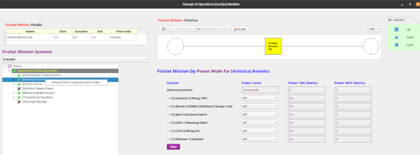
If you have mistakenly selected a subsystem or have later decided not to define the subsystem’s power modes in terms of the power levels of its components, go to the System Tree, right-click on that subsystem, and select “Remove from computed item modes” – that will immediately remove the subsystem’s mode definition from the computed modes, so its power modes can be specified directly by selecting power levels.
A Cyclic Activity can be added by dragging the “Cycle” icon from the Activity Palette and dropping it onto the Timeline, as shown:

When the drop action has completed, the resulting Cyclic Activity will be displayed:

A Cyclic Activity has its own associated Timeline that represents one of its cycles. The Timeline for the Cyclic Activity can be defined as follows:
Select the Cyclic Activity by clicking on it – it will turn yellow.
Double-click on the Cyclic Activity and an empty Timeline will be displayed:

Add Activity blocks by drag / dropping them, as in the system Timeline.
Edit the names, durations, and time units of the Activity blocks as before, by clicking on a cell in the Activity Details table on the left and hit Enter or simply click on another cell when done.
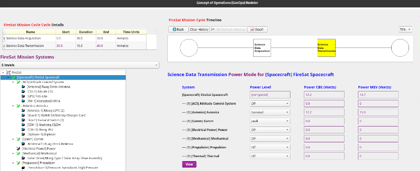
To display a graph of the System Power Modes vs. Time, simply click on the Graph button above the Timeline:
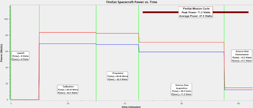
The graph can be saved as either a “.png” or “.pdf” file.
Note that when one of the activities in the Timeline is a Cyclic Activity, only one cycle will be shown in the graph. The graph will show the Peak Power and Average Power values for the cycle. The ConOps Tool is also capable of defining cycles within cycles and graphing them, if a mission Timeline contains them.
Any row in the Objects table can be double-clicked to display that object in the Object Viewer/Editor. The Objects table can be sorted on any column by clicking on that column’s heading. Columns can be rearranged by drag/drop, and you can select which columns you want displayed for a given object type by right-clicking on the headers, which displays a context menu, and choosing the select columns option, which will display all the attributes of the current object type and you can just check the attributes you want to see and uncheck the ones to hide. Gargleblaster will remember your choices and will use them the next time you go into Local DB mode.
Preferred units can be set using either the Edit Preferences item in the Tools menu or by right-clicking on the Systems Dashboard headers and selecting set preferred units. When you have set the preferred units for a specified set of dimensions, Gargleblaster will use your preferred units when displaying any parameter that has those dimensions in both the Systems Dashboard and the Object Viewer/Editor, and your preference is saved and used in all future sessions.